In this tutorial we focus only on GPIO pins of ESP8266 and How to use efficiently ?
ESP8266 comes in many variants most popular is ESP-12 and ESP-01. Use of ESP8266 as just a Serial-to-WiFi bridge with arduino is most common mistake newbies do. ESP8266 itself is very powerful microcontroller. Lets compare with Arduino with ESP8266. To get serial and IOs expantion like Arduino you can use NodeMCU. Difference between ESP12, ESP01 and NodeMCU is only of Flash memory and Number of IOs are available to user. Programming and functioning of all three devices is same.
ESP8266 (NodeMCU) vs Arduino UNO
| Specification | Arduino | ESP8266 |
| RAM | 4K Bytes | 80 Kilobytes |
| FLASH memory | 32 Kilo bytes | 4 Mega Bytes |
| Speed | 16MHz | 80MHz |
| GPIOs | 14 | 11 |
| IO Voltage Level | 5V | 3.3V |
| ADC | 6 (10-bit) | 1 (10-Bit) |
| Serial | 1 | 1 |
| I2C | 1 | 1 |
| SPI | 1 | Used by Flash Chip |
| PWM IOs | 6 (8-Bit Resolution) | All IO Pins with 10-Bit Resolution |
| WiFi | NO | YES 2 MBPS |
Digital I/O of ESP8266
Before we start on GPIO programming of ESP8266, let’s see pinouts of each type.
ESP8266 ESP-12 Pinout
How it Looks ?

Never use SPI IO Lines present on bottom side. They are used by flash chip. use of this IO lines will crash the ESP prgram.
ESP8266 ESP-01 Pinout
How it Looks ?

Its small comes with only four IO lines. Its small size makes it perfect for controlling of electrical appliances (IoT).
ESP8266 NodeMCU Pin Description

NodeMCU pins are confusing with actual numbers on the board.
How it Looks ?

Don’t confuse your self seeing lots of pins on NodeMCU, having too many IOs. It has only 11-Usable IO lines.
GPIO Pin Description
Just like a normal Arduino, the ESP8266 has digital input/output pins (I/O or GPIO, General Purpose Input/Output pins). These digital input/outputs operate at 3.3V. NEVER CONNECT 5V TO ANY PIN OF ESP8266. The pins are not 5V tolerant, applying more than 3.6V on any pin will kill the chip. The maximum current that can be drawn from a single GPIO pin is 12mA.
3.3V to 5V circuit interface
In many application we need to connect 5V circuits with ESP8266 this can be achieved with use of simple resistor and diode as shown in below.

Usable pins
The ESP8266 has 17 GPIO pins (0-16), however, you can only use 11 of them, because 6 pins (GPIO 6 – 11) are used to connect the flash memory chip. This is the small 8-pin IC right next to the ESP8266. If you try to use one of these pins, you might crash your program.
GPIO 1 and 3 are used as TX and RX of the hardware Serial port (UART), so in most cases, you can’t use them as normal I/O while sending/receiving serial data.
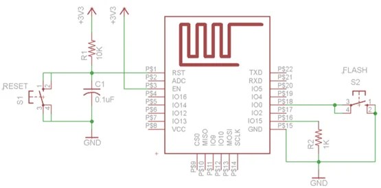
Boot modes
Few I/O pins have a special function during boot: They select 1 of 3 boot modes:
| GPIO15 | GPIO0 | GPIO2 | Mode |
| 0V | 0V | 3.3V | Uart Bootloader |
| 0V | 3.3V | 3.3V | Boot sketch (SPI flash) |
| 3.3V | X | X | SDIO mode (not used for Arduino) |
Read more on How to program ESP8266?
Note: Pull down of 1KOhm is required on GPIO0 and external pull-up resistor on GPIO2 is not required the internal pullup is enabled at boot.
- GPIO15 is always pulled low, so you can’t use the internal pull-up resistor. You have to keep this in mind when using GPIO15 as an input to read a switch or connect it to a device with an open-collector (or open-drain) output, like I²C.
- GPIO0 is pulled high during normal operation.
- GPIO2 can’t be low at boot, so you can’t connect a switch to it.
Internal pull-up/-down resistors
GPIO 0-15 all have a built-in pull-up resistor, just like in an Arduino. GPIO16 has a built-in pull-down resistor.
Digital I/O
Just like with a regular Arduino, you can set the function of a pin using pinMode(pin, mode); where pin is the GPIO number*, and mode can be either INPUT, which is the default, OUTPUT, or INPUT_PULLUP to enable the built-in pull-up resistors for GPIO 0-15. To enable the pull-down resistor for GPIO16, you have to use INPUT_PULLDOWN_16.
(*) NodeMCU uses a different pin mapping, read more here. To address a NodeMCU pin, e.g. pin 5, use D5: for instance: pinMode(D5, OUTPUT);
To set an output pin high (3.3V) or low (0V), use digitalWrite(pin, value); where pin is the digital pin, and value either 1 or 0 (or HIGH and LOW).
To read an input, use digitalRead(pin);
PWM
ESP8266 software PWM is supported on all digital pins. The default PWM range is 10-bits @ 1kHz, but this can be changed.
To enable PWM on a certain pin, use analogWrite(pin, value); where pin is the digital pin, and value a number between 0 and 1023.
You can change the range (bit depth) of the PWM output by using analogWriteRange(range);
The frequency can be changed by using analogWriteFreq(frequency);. frequency should be between 100 and 1000Hz.
Analog input Read More
The ESP8266 has a single analog input, with an input range of 0 – 1.0V. If you supply 3.3V, for example, you will damage the chip. Some boards like the NodeMCU have an on-board resistive voltage divider, to get an easier 0 – 3.3V range.
The ADC (analog to digital converter) has a resolution of 10 bits.
The ESP can also use the ADC to measure the supply voltage (VCC). To do this, include ADC_MODE(ADC_VCC); at the top of your sketch, and use ESP.getVcc(); to actually get the voltage. If you use it to read the supply voltage, you can’t connect anything else to the analog pin.
Serial Communication

The ESP8266 has two hardware UARTS (Serial ports):
UART0 on pins 1 and 3 (TX0 and RX0 resp.), and UART1 on pins 2 and 8 (TX1 and RX1 resp.), however, GPIO8 is used to connect the flash chip. This means that UART1 can only transmit data.
UART0 also has hardware flow control on pins 15 and 13 (RTS0 and CTS0 resp.). These two pins can also be used as alternative TX0 and RX0 pins.
To use UART0 (TX = GPIO1, RX = GPIO3), you can use the Serial object, just like on an Arduino: Serial.begin(baud).
To use the alternative pins (TX = GPIO15, RX = GPIO13), use Serial.swap() after Serial.begin.
To use UART1 (TX = GPIO2), use the Serial1 object.
WiFi Communication
ESP can be operated in both HotSpot mode and it can connect to hot spot. Both mode can work at a time.
Read this simple example of wifi communication
One thing to keep in mind while writing programs for the ESP8266 is that your sketch has to share resources (CPU time and memory) with the Wi-Fi- and TCP-stacks (the software that runs in the background and handles all Wi-Fi and IP connections). If your code takes too long to execute, and don’t let the TCP stacks do their thing, it might crash, or you could lose data. It’s best to keep the execution time of you loop under a couple of hundreds of milliseconds.
Every time the main loop is repeated, your sketch yields to the Wi-Fi and TCP to handle all Wi-Fi and TCP requests.
If your loop takes longer than this, you will have to explicitly give CPU time to the Wi-Fi/TCP stacks, by using including delay(0); or yield();. If you don’t, network communication won’t work as expected, and if it’s longer than 3 seconds, the soft WDT (Watch Dog Timer) will reset the ESP. If the soft WDT is disabled, after a little over 8 seconds, the hardware WDT will reset the chip.