ESP8266 is most popular IoT module, it performs almost all the need of IoT functions in small size with powerful processor and huge program memory of 512Kbytes and RAM of 80 Kbytes.
This tutorial gives some information on how to get started using a ESP8266-based board. It is intended for the newbie with past experience in arduino-like mcu who wants to get a first hand at ESP8266.
In this tutorial we start with minimum hardware required and software setup.
Which ESP board?
ESP8266 usually comes assembled on a board, the most popular ones having been the ESP-NN (ESP-12, ESP-01, etc) by vendors such asAIThinkers. Olimex has also started to sell their own boards, and you can find several others too. The boards integrate an ESP8266 chip plus a Flash memory chip (Flash RAM), a crystal, and usually on on-board WiFi antenna. The Flash RAM size and chip model can vary.


Among the ESP-XX boards, the most notable to get started is the ESP-12 and ESP-01, ESP-01 has a male 2×4 0.1“ pitch connector that can be readily used with Dupont wires. This board exposes serial communication pins (RX/TX), and the minimal 4 control pins, GPIO0, GPIO2, CH_PD and ReSeT, plus VCC and GND of course. With this board you will have very limited access to all-purpose GPIOs. It also has an on-PCB Wifi Antenna etched on the PCB, which has sufficient gain for shorter range applications.
The other ESP-12 modules expose more GPIO pins, but are packaged in SMT packages, at best with a 2mm-pitch notches. Some modules have etched antenna, some have ceramic antenna, and some have just a socket or a pin. A favorite for that is the ESP-12, which has a shield (with FCC marking, but probably not registered at FCC) and also single channel 10-bit ADC.
This is the complete hardware setup required to start with ESP8266. You can use 5V from USB also. For 3.3V Serial voltage levels no need of D1 and R3 resistors. To drive RGB LEDs, Relays use ULN2003 as driver IC. ESP8266 have PWM feature you can use it for fading the LEDs.
Let’s move towards software requirements of ESP8266 and its setup.

Software Setup for ESP8266
ESP can be programmed using Arduino Software or using AT commands. In this tutorial we are using Arduino software.
Use of AT commands requires additional controller to generate AT commands. Use of AT commands give you advantage of extra IOs of controller.
Direct flashing of ESP8266 using arduino gives many benefits such as no need of external controller, Program memory of 1 M bytes and RAM of 80K Bytes, Makes simple hardware and software.
Let me clear you first Programming of IoT esp8266 is done in Arduino software and uses same commands that we use for Arduino Uno.
Steps for software setup
Step 1: Download latest Arduino Software from www.arduino.cc
Starting with 1.6.4, Arduino allows installation of third-party platform packages using Boards Manager. Use 1.6.4 or higher version of Arduino software.
Step 2: Download Arduino Core for ESP8266 WiFi Chip from GitHub
Download Link (https://github.com/esp8266/Arduino/)
Arduino Core for ESP8266 project brings support for ESP8266 chip to the Arduino environment. It lets you write sketches using familiar Arduino functions and libraries, and run them directly on ESP8266, no external microcontroller required.
ESP8266 Arduino core comes with libraries to communicate over WiFi using TCP and UDP, set up HTTP, mDNS, SSDP, and DNS servers, do OTA updates, use a file system in flash memory, work with SD cards, servos, SPI and I2C peripherals.
Step 3: Installing with Boards Manager
Starting with 1.6.4, Arduino allows installation of third-party platform packages using Boards Manager. ESP8266 packages are available for Windows, Mac OS, and Linux (32 and 64 bit).
Install Arduino 1.6.8 from the Arduino website.
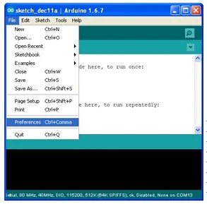
Start Arduino and open Preferences window.
Enter http://arduino.esp8266.com/stable/package_esp8266com_index.json into Additional Board Manager URLs field. You can add multiple URLs, separating them with commas.

Open Boards Manager from Tools > Board menu and install esp8266 platform (and don’t forget to select your ESP8266 board from Tools > Board menu after installation).

Select ESP8266 then press install

This package installation is from internet, your computer must be connected to internet it is around 250 MBytes. Read details on GitHub.
After installation of ESP8266 packages for Arduino, Select board Generic ESP8266 or ESPino ESP12. Open examples >> ESP8266 >> LED blink and try compiling it.

If it complies successfully skip step 4. To flash the program in ESP8266, press and hold Flash (S2) button and momentarily press Reset button and then release Flash button.
Press upload button from your Arduino window. Program will start uploading.
After uploading onboard blue LED will start to blink. If you passed this blink test you are ready to go further.
Step 4 (If required): After installing everything, you may find trouble in compiling missing .h files
Go to your arduino installation folder (where your arduino.exe is) in this folder create folder “portable”
Copy and paste copy from “C:\Documents and Settings\Administrator\Application Data\Arduino” (check that this address is shown while compilation error missing .h file)
Copy all contains (folder naming “packages” and “staging” and surrounding files)
Paste the copied contains in “portable” folder that you created in Arduino folder.
Check that compilation works now. If all ok go ahead to test it on hardware