ESP8266 have 10 GPIO pins and 1 Analog Input. Pin numbers in Arduino correspond directly to the ESP8266 GPIO pin numbers. pinMode, digitalRead, and digitalWrite functions work as usual, so to read GPIO2, call digitalRead(2).
Digital IO (GPIO)
Digital pins 0—15 can be INPUT, OUTPUT, or INPUT_PULLUP. Pin 16 can be INPUT, OUTPUT or INPUT_PULLDOWN_16. At startup, pins are configured as INPUT.
Pins may also serve other functions, like Serial, I2C, SPI. These functions are normally activated by the corresponding library. The diagram below shows pin mapping for the popular ESP-12 module.
GPIO0 is pulled low during programming (flashing), To prevent ESP going in programming mode by external input. Use this pin for output only.
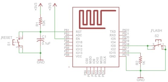
Digital pins 9—14 are not connected in this diagram because they are used to connect flash memory chip on most modules. Trying to use these pins as IOs will likely cause the program to crash.
Note that some boards and modules (ESP-12ED, NodeMCU 1.0) also break out pins IO9 and IO10. These may be used as IO if flash chip works in DIO mode (as opposed to QIO, which is the default one).
Pin interrupts are supported through attachInterrupt, detachInterrupt functions. Interrupts may be attached to any GPIO pin, except GPIO16. Standard Arduino interrupt types are supported: CHANGE, RISING, FALLING.
Analog input
ESP8266 has a single ADC channel available to users. It may be used either to read voltage at ADC pin, or to read module supply voltage (VCC).
To read external voltage applied to ADC pin, use analogRead(A0). Input voltage range is 0— 1.0V.
To read VCC voltage, use ESP.getVcc() and ADC pin must be kept unconnected. Additionally, the following line has to be added to the sketch: ADC_MODE(ADC_VCC);
This line has to appear outside of any functions, for instance right after the #include lines of your sketch.
Analog output (PWM)
analogWrite(pin, value) enables software PWM on the given pin. PWM may be used on pins 0 to 16. Call analogWrite(pin, 0) to disable PWM on the pin. value may be in range from 0 to PWMRANGE, which is equal to 1023 by default. PWM range may be changed by calling analogWriteRange(new_range). PWM frequency is 1kHz by default. Call analogWriteFreq(new_frequency) to change the frequency.
Serial
Read More on Serial Programming Here
Serial object works much the same way as on a regular Arduino. Apart from hardware FIFO (128 bytes for TX and RX) HardwareSerial has additional 256-byte TX and RX buffers. Both transmit and receive is interrupt-driven. Write and read functions only block the sketch execution when the respective FIFO/buffers are full/empty.
Serial uses UART0, which is mapped to pins GPIO1 (TX) and GPIO3 (RX). Serial may be remapped to GPIO15 (TX) and GPIO13 (RX) by calling Serial.swap() after Serial.begin. Calling swap again maps UART0 back to GPIO1 and GPIO3. Serial1 uses UART1, TX pin is GPIO2. UART1 can not be used to receive data because normally it’s RX pin is occupied for flash chip connection. To use Serial1, call Serial1.begin(baudrate). If Serial1 is not used and Serial is not swapped – TX for UART0 can be mapped to GPIO2 instead by calling Serial.set_tx(2) after Serial.begin or directly with Serial.begin(baud, config, mode, 2). By default the diagnostic output from WiFi libraries is disabled when you call Serial.begin. To enable debug output again, call Serial.setDebugOutput(true). To redirect debug output to Serial1 instead, call Serial1.setDebugOutput(true).
You also need to use Serial.setDebugOutput(true) to enable output from printf() function.
Both Serial and Serial1 objects support 5, 6, 7, 8 data bits, odd (O), even (E), and no (N) parity, and 1 or 2 stop bits. To set the desired mode, call Serial.begin(baudrate, SERIAL_8N1), Serial.begin(baudrate, SERIAL_6E2), etc.
A new method has been implemented on both Serial and Serial1 to get current baud rate setting. To get the current baud rate, call Serial.baudRate(), Serial1.baudRate(). Return a int of current speed.
Software Serial Explained Here
I2C (Wire library)
Wire library currently supports master mode up to approximately 450KHz. Before using I2C, pins for SDA and SCL need to be set by calling Wire.begin(int sda, int scl), i.e. Wire.begin(0, 2) on ESP-01, else they default to pins 4(SDA) and 5(SCL).